
Physical Models and Demonstrations
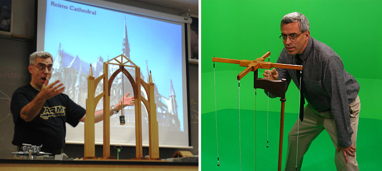
Based on two decades’ experience as an engineering educator, Steve Ressler has found that many concepts in physics, mechanics, civil engineering, and mechanical engineering are most effectively illustrated through the use of physical models and demonstrations. Unlike computer-generated animations, physical models are subject to the same laws of physics that govern the behavior of the real-world systems they represent. Thus, physical models are often far more convincing than computer animations in illustrating physical phenomena.
Consistent with this observation, Steve has designed and built a wide variety of physical models for use in engineering courses and presentations. A few representative samples from his workshop are shown below. Several others are highlighted on the Great Courses and Public Speaking pages of this website.
Water Wheels
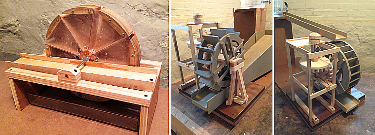
The model at left is a rotary water-lifting machine called a tympanum, from the 3rd century BC. The typanum consists of a hollow drum (which is the basis for its name), divided into eight wedge-shaped compartments. When the bottom of the wheel is immersed in a sump, water enters the lower compartments through slots in its outer rim. As each compartment rotates upward, the water pours out of a circular hole near the axle and flows into an elevated trough, which delivers the water to its destination. In antiquity, the drum was powered by a man treading on top of the outer rim.
The other two devices are water wheels, used to power grain mills throughout the ancient Roman world. The one in the center is called an undershot wheel, because it was driven by water flowing underneath the wheel. The one at right is called an overshot wheel, because it was rotated by water pouring into buckets at the top of the wheel. Both types turned a millstone through right-angle gearing, as shown in the photo at right.
Aqueducts and Water Supply
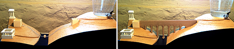
This model illustrates the two different aqueduct configurations used in the ancient world. At left is a Hellenistic-era inverted siphon system, which carries water from its source (an aquifer) to its destination (a city water distribution system) through a pipeline, represented by the plastic tubing in this model. Because water flows through the sealed pipe under pressure, the pipeline can be routed through the valley without hindering its flow. At right is a Roman open channel system, in which water flows through an open conduit. To function properly, the open channel must have a gradual downhill gradient; thus it must be carried across the valley on an arched bridge.
Flat Arch
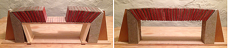
This model demonstrates the structural behavior of a Roman flat arch (also called a lintel arch), which uses slightly wedge-shaped bricks to span a horizontal gap. Note that the individual bricks in this model are not connected together with any adhesive or mechanical fasteners. They are held together entirely by compression, caused by “wedge action” of the individual elements.
Archimedes Screw
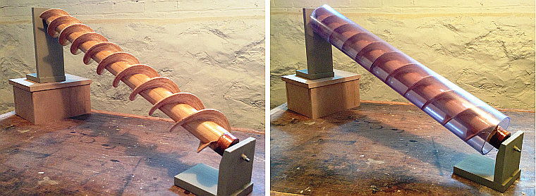
This device is a human-powered rotary water pump, generally attributed to the great Greek mathematician and inventor Archimedes. It is also the world’s first known use of the screw as a mechanical device. As you can see from Steve’s computer model of the same machine, the outer casing of the original pump was made of wooden staves held together with iron bands. Steve used a plastic pipe in his physical model (at right) so its operation could be seen more clearly.
Octagonal Dome
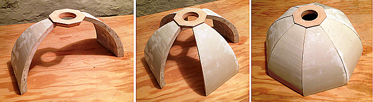
This model illustrates how a dome can be visualized as a series of arches arranged radially around a vertical axis. The central opening, called an oculus, is really just a 3-dimensional keystone that happens to have a hole in the middle.
Groined Vaulting
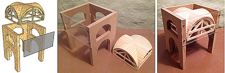
This model illustrates how Roman engineers enclosed basilicas and baths by constructing elaborately curved groined vaulting, made of cast concrete. Wooden formwork (called centering) is used to establish the shape of the vault, and then concrete (not shown) is poured on top. After the concrete has cured, the centering is removed.
“The shapes arise!
The shape measur’d, saw’d, jack’d, join’d, stain’d…”
~Walt Whitman
For updates, events, and discussion:
![]()