This page documents the physical models that will be used in the Great Courses lecture series “Epic Engineering Failures.” New photos will be posted as new models are completed.
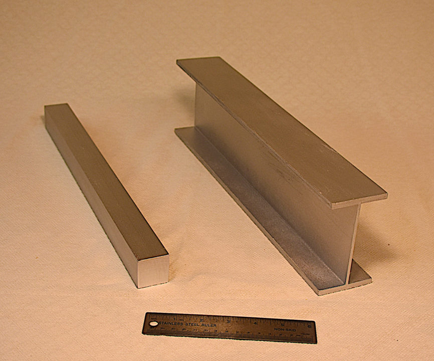
Demo 2.3 – Square and I-shaped beams
These models demonstrate in influence of cross-section geometry on beam strength and stiffness. Both the square and I-shaped beams use the same amount of material, but the I-shaped beam is roughly ten times stronger. Both models are painted wood. A 6-inch ruler is shown for scale.
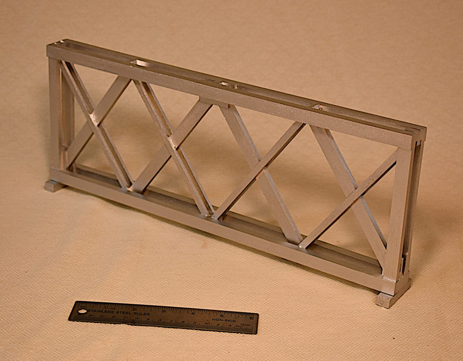
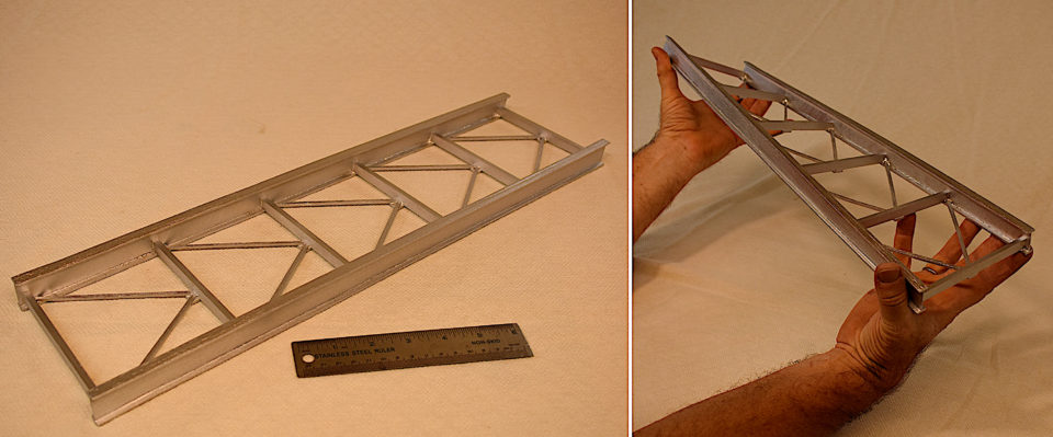
Demo 3.1 – Lattice girder
This model illustrates the configuration of the lattice girders used in the Firth of Tay Bridge. The models is painted wood. A 6-inch ruler is shown for scale.
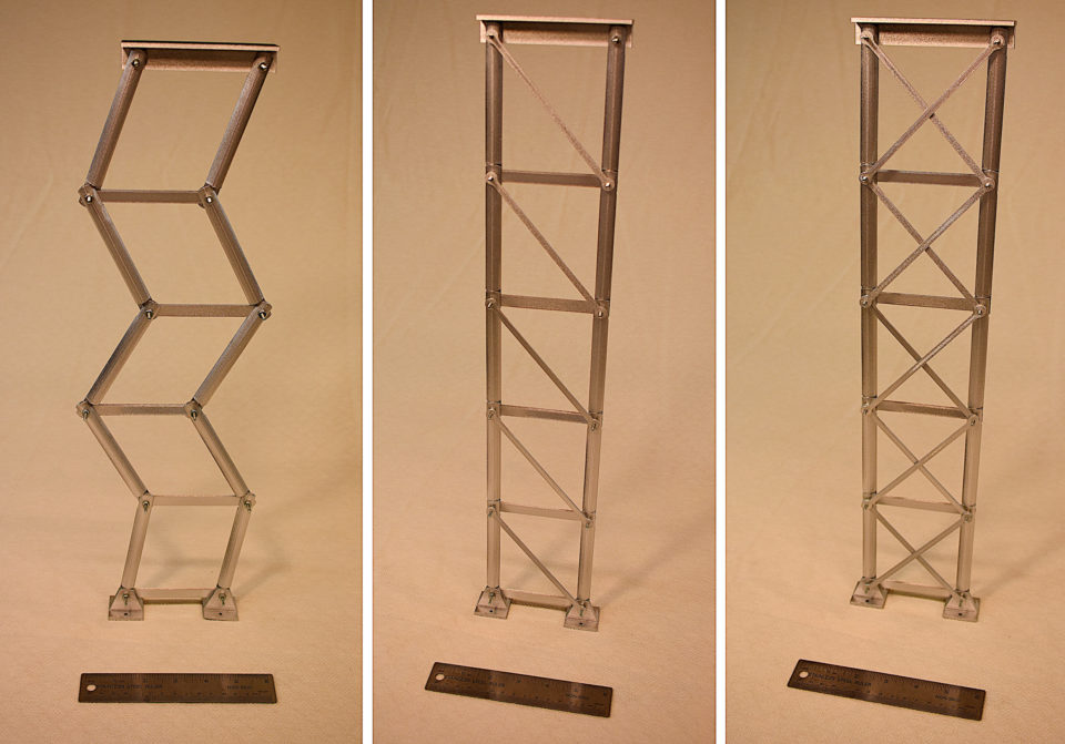
Demo 3.2, 3.3, 3.4, & 3.6 – Trussed bridge pier
This model is a simplified representation of the piers that supported the Firth of Tay Bridge. The model illustrates the requirements for stability of a truss structure, the role of single and doubled diagonals (X-bracing), and the possible failure modes of the Tay Bridge piers. The models is 3D-printed PLA plastic. A 6-inch ruler is shown for scale.
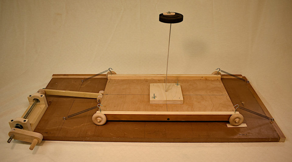
Demo 5.16 – Earthquake simulator (“shake table”) and column-mass structural model
This model is used to simulate an earthquake by generating reciprocating horizontal ground motion from a rotary input (provided by either hand-cranking or a variable-speed electric drill). The model is primarily wood but uses metal for mechanical fittings and shafts. Shown on the shake table is a single-degree-of-freedom column-mass model, which is used to illustrate the concepts of natural frequency and resonance. The column is an aluminum bar. The base of the shake table measures 30 inches by 16 inches.
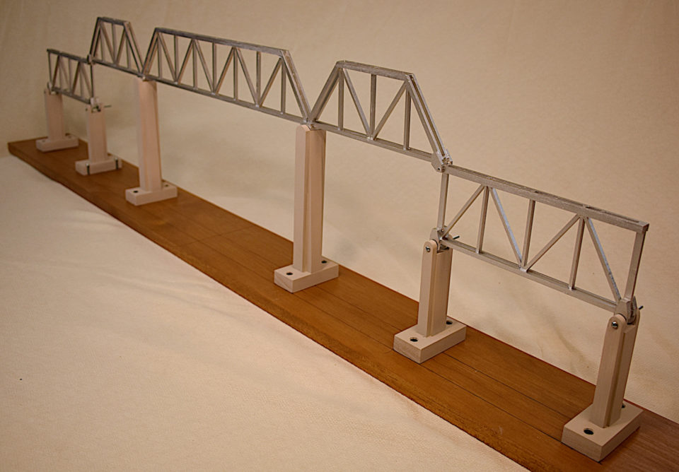
Demo 6.1 – Sunshine Skyway Bridge implemented as five simple spans
This model illustrates how the Sunshine Skyway bridge might have been implemented as five individual simply supported spans. The model is painted wood and is 48 inches long.
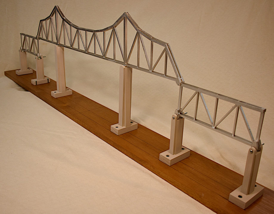
Demo 6.2 – Sunshine Skyway Bridge implemented with three continuous spans
This model illustrates how the Sunshine Skyway bridge might have been implemented with three continuous spans (plus two simple approach spans). The model shows how the continuous spans are more structurally efficient and more redundant but also more computationally complex. The model is painted wood and is 48 inches long.
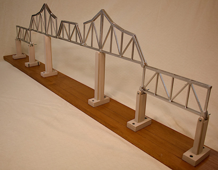
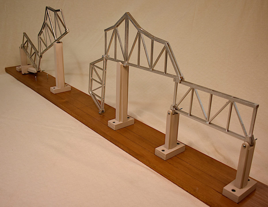
Demo 6.3 – Sunshine Skyway Bridge implemented as a cantilever
This model illustrates how the Sunshine Skyway bridge was actually implemented with the cantilever configuration. The model shows how the cantilever configuration achieves structural efficiency comparable to that of the continuous bridge but without the computational complexity. The model is also used to illustrate the failure mode of the Sunshine Skyway Bridge and to make the point that its lack of structural redundancy greatly increased the severity of the collapse. The model is painted wood and is 48 inches long.
Demo 6.5 – Simple truss with buckling top chord
This model illustrates the failure mode of the Skagit River Bridge. Initially, with the top chord unbraced, the chord buckles easily when the truss is loaded. But when the vertical brace is added, the buckling strength of the top chord increases by a factor of four. Thus, in the Skagit River Bridge, when this vertical brace was compromised by the vehicular collision, the top chord buckled and the bridge collapsed. The models is 3D-printed PLA plastic. A 6-inch ruler is shown for scale.
Demo 9.3 – Tacoma Narrows Bridge stiffening girder and wind bracing system
This model illustrates the stiffening girder and wind bracing system used in the Tacoma Narrows Bridge and is used to show that this configuration was particularly susceptible to torsional (twisting) deformations. The models is painted wood. A 6-inch ruler is shown for scale.
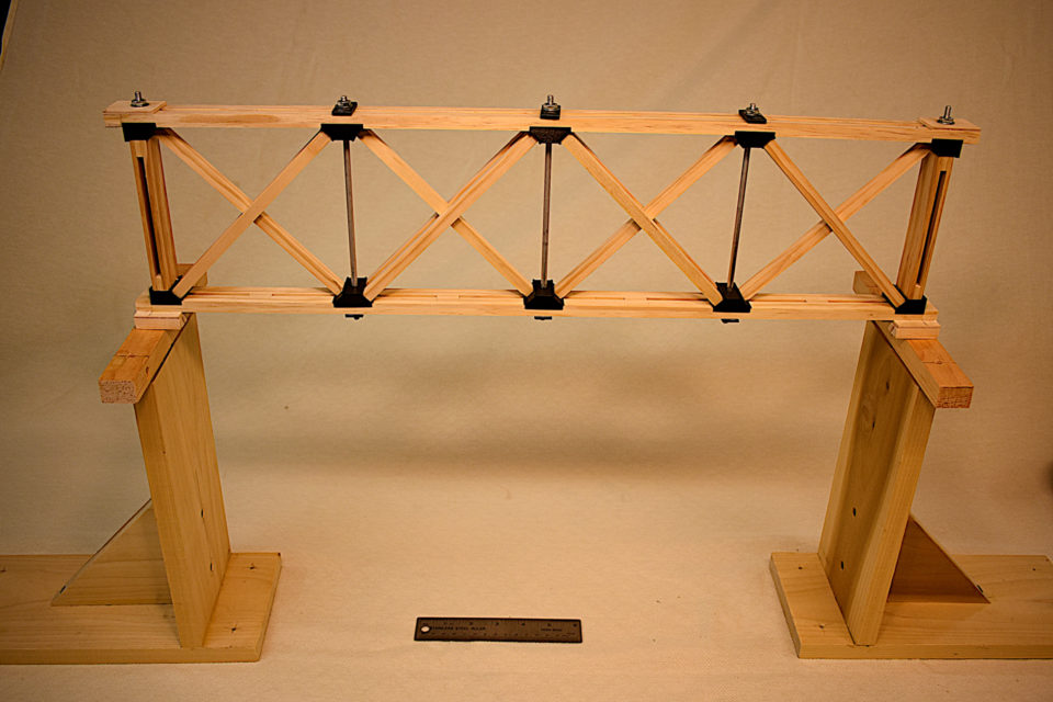
Demo 13.1 – Wooden Howe Truss
This model illustrates the configuration of the (primarily) wooden Howe truss that was the basis for Amasa Stone’s all-iron Ashtabula Bridge. This model is used to illustrate the process of post-tensioning to enhance the structural integrity of the truss. The model is primarily wood with aluminum tension rods and 3D-printed PLA plastic angle blocks. It can be fully disassembled. A 6-inch ruler is shown for scale.
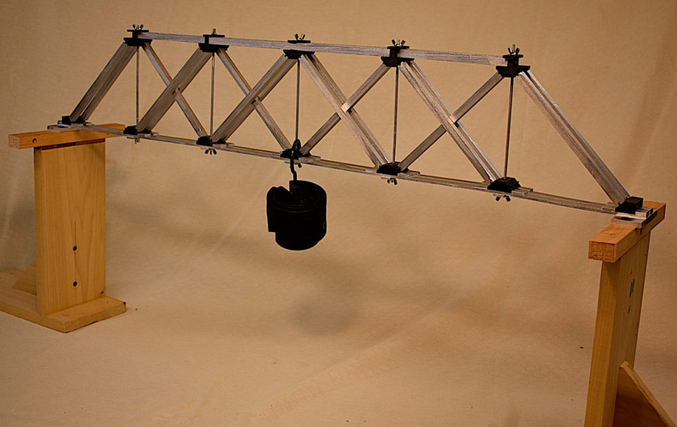
Demo 13.8 – Ashtabula Bridge truss
This model is a simplified representation of the all-iron Howe Truss designed by Amasa Stone for the Ashtabula Bridge. It is used to illustrate how the truss was assembled and post-tensioned, as well as how it failed. The model can be fully disassembled but is extremely difficult to assemble and “tune”–a direct reflection of the fundamental flaws in Stone’s design. The model is primarily painted wood with aluminum tension rods and 3D-printed PLA plastic angle blocks. A 6-inch ruler is shown for scale.

